Breadboard Ethernet, part 1
I did this project a year and a half ago, but I only got around to posting about it now. This is part 1 of 2.
There are plenty of ways to add Ethernet to an Arduino-compatible, most based around one of the WizNet chips. This is probably the best way to go if you just want to get Ethernet connectivity in the easiest way possible.
However, I noticed that there is an Ethernet controller, ENC28J60, which is available in a DIP package. I think it’s fun to wire things up myself instead of just using a pre-built module, so I thought I’d try breadboarding a circuit with the ENC28J60.
The one component of the circuit which won’t fit on a breadboard is the MagJack, so I made a simple breakout board to allow the MagJack to be plugged into a breadboard.
Schematic
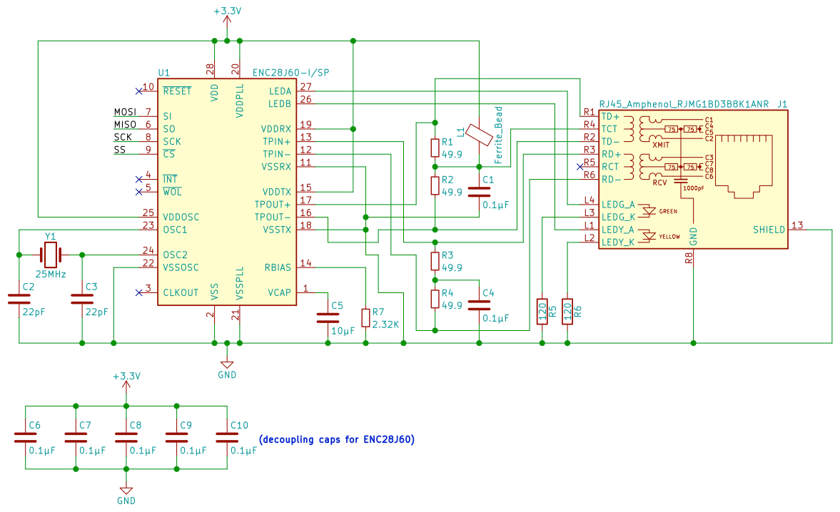
Bill of Materials
| Ref | Description | MPN | Digi-Key PN |
|---|---|---|---|
| C1, C4, C6-C10 | CAP CER 0.1UF 50V X7R RADIAL | K104K10X7RF5UH5 | BC2665CT-ND |
| C2, C3 | CAP CER 22PF 50V C0G/NP0 RADIAL | K220J15C0GF5TL2 | BC1005CT-ND |
| C5 | CAP CER 10UF 10V X7R RADIAL | FG24X7R1A106KRT06 | 445-173370-1-ND |
| J1 | CONN MAGJACK 1PORT 10/100 BASE-T | RJMG1BD3B8K1ANR | RJMG1BD3B8K1ANR-ND |
| L1 | FERRITE BEAD 135 OHM AXIAL 1LN | 28L0138-40R-10 | 240-2439-1-ND |
| R1-R4 | RES 49.9 OHM 1/4W 1% AXIAL | RNF14FTD49R9 | RNF14FTD49R9CT-ND |
| R5, R6 | RES 120 OHM 1/4W 5% AXIAL | CF14JT120R | CF14JT120RCT-ND |
| R7 | RES 2.32K OHM 1/4W 1% AXIAL | RNF14FTD2K32 | RNF14FTD2K32CT-ND |
| U1 | IC ETHERNET CTRLR W/SPI 28SDIP | ENC28J60-I/SP | ENC28J60-I/SP-ND |
| Y1 | CRYSTAL 25.0000MHZ 20PF T/H | ATS25A-E | CTX1142-ND |
| ATMEGA328 ARDUINO PRO MINI 3.3V | DEV-11114 | 1568-1054-ND |
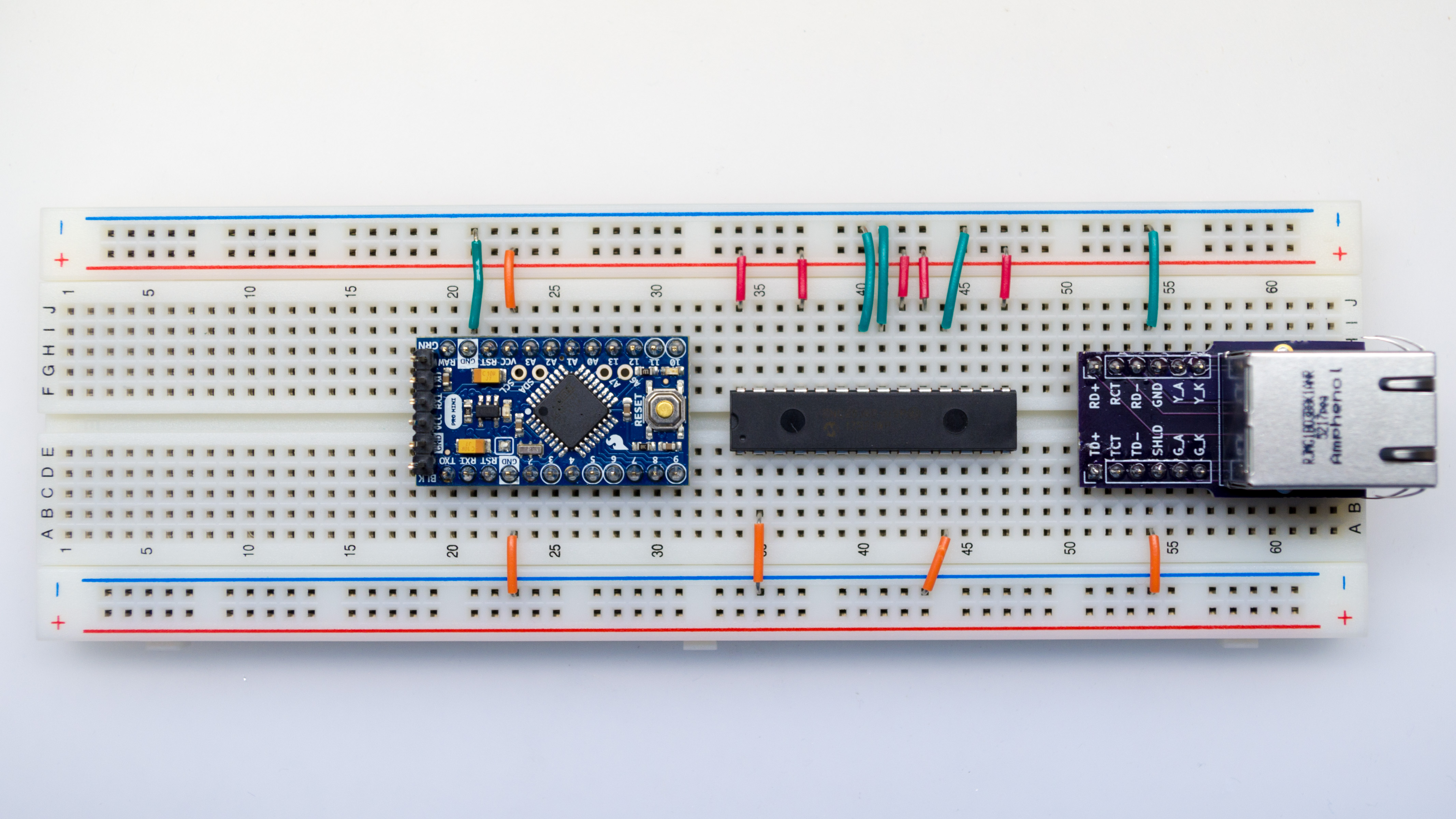
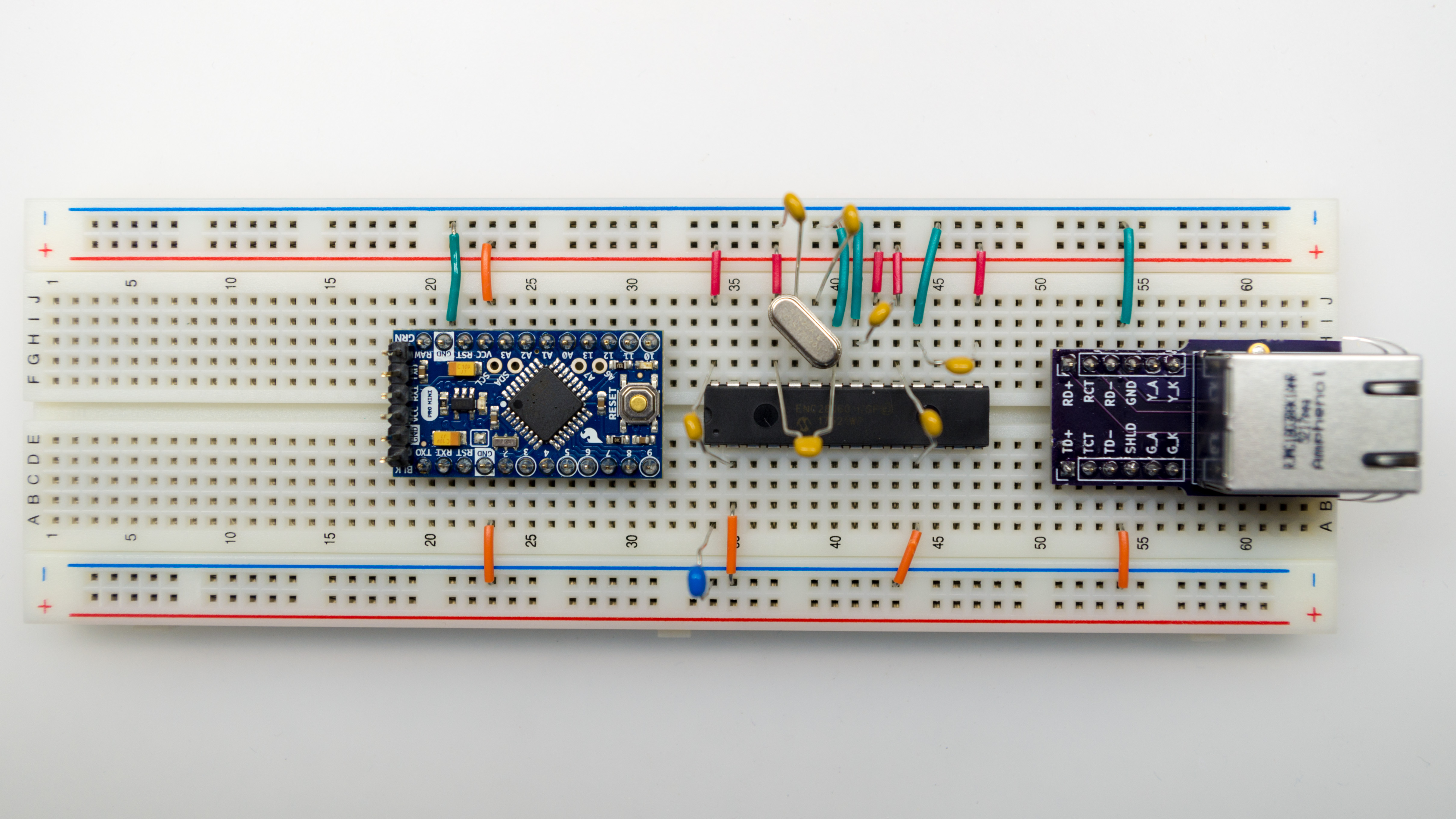
Hookup
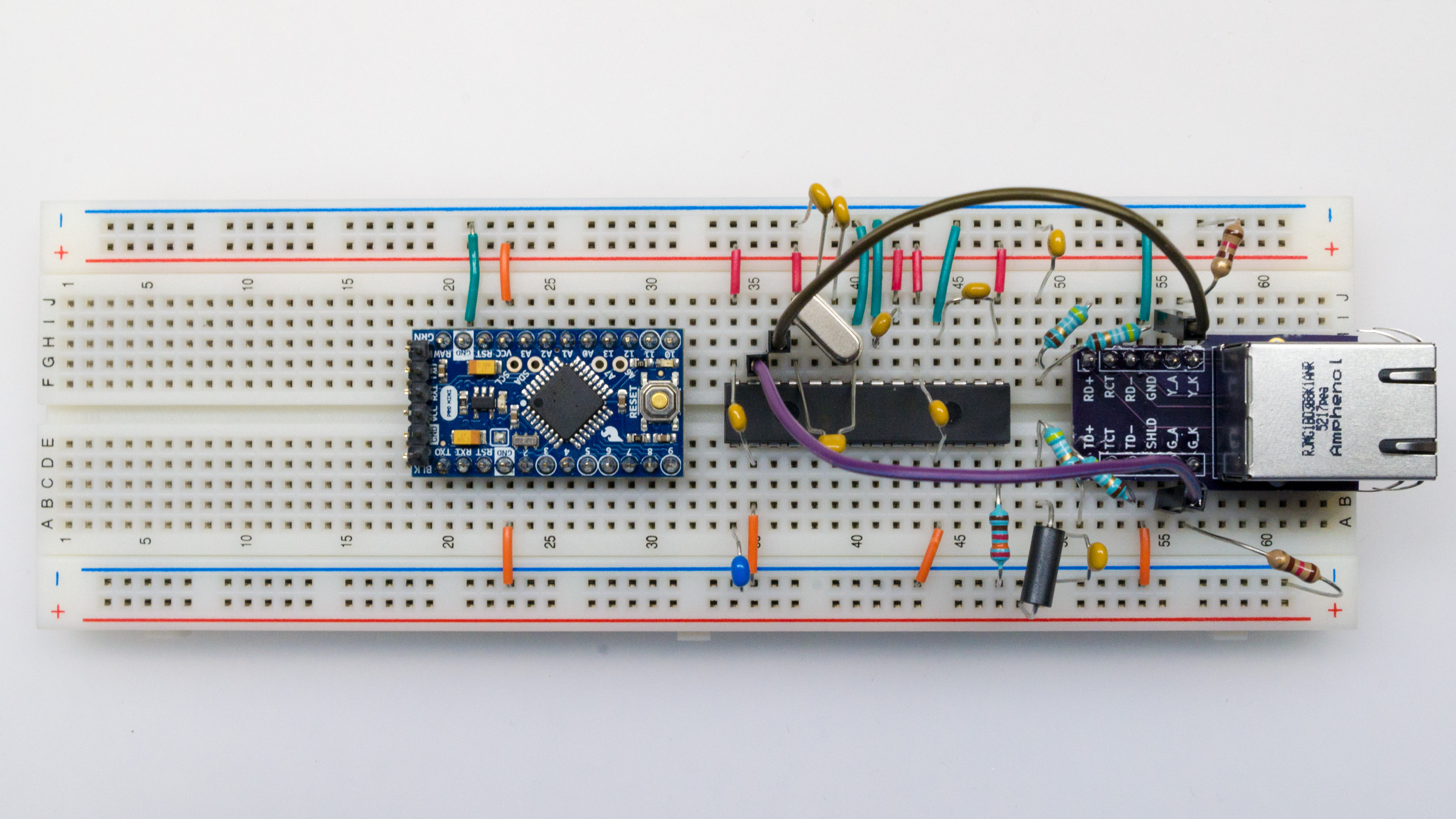
Start out by connecting wires to power and ground.
- On Arduino Pro Mini, two GND pins go to GND, VCC pin goes to VCC.
- On ENC28J60, pins 2, 11, 18, 21, and 22 go to GND.
- On ENC28J60, pins 15, 19, 20, 25, and 28 go to VCC.
- On Magjack, GND and SHLD pins go to GND.
Add 0.1µF decoupling capacitors on ENC28J60.
- Between 15 (VDDTX) and 18 (VSSTX)
- Between 19 (VDDRX) and 11 (VSSRX)
- Between 20 (VDDPLL) and 21 (VSSPLL)
- Between 25 (VDDOSC) and 22 (VSSOSC)
- Between 28 (VDD) and 2 (VSS)
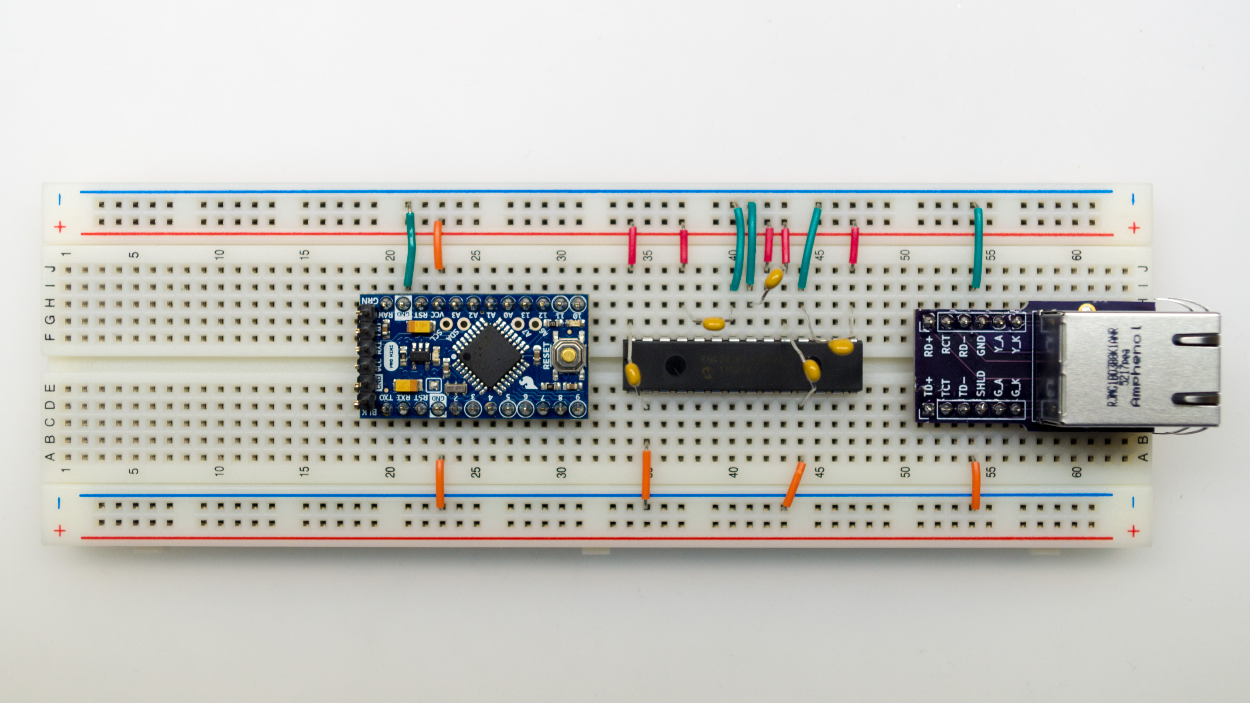
Add 10μF capacitor between VCAP (pin 1) and GND.
Add 25 MHz crystal between OSC1 and OSC2 (pins 23 and 24). Add a 22pF capacitor between OSC1 and GND, and another 22pF capacitor between OSC2 and GND.
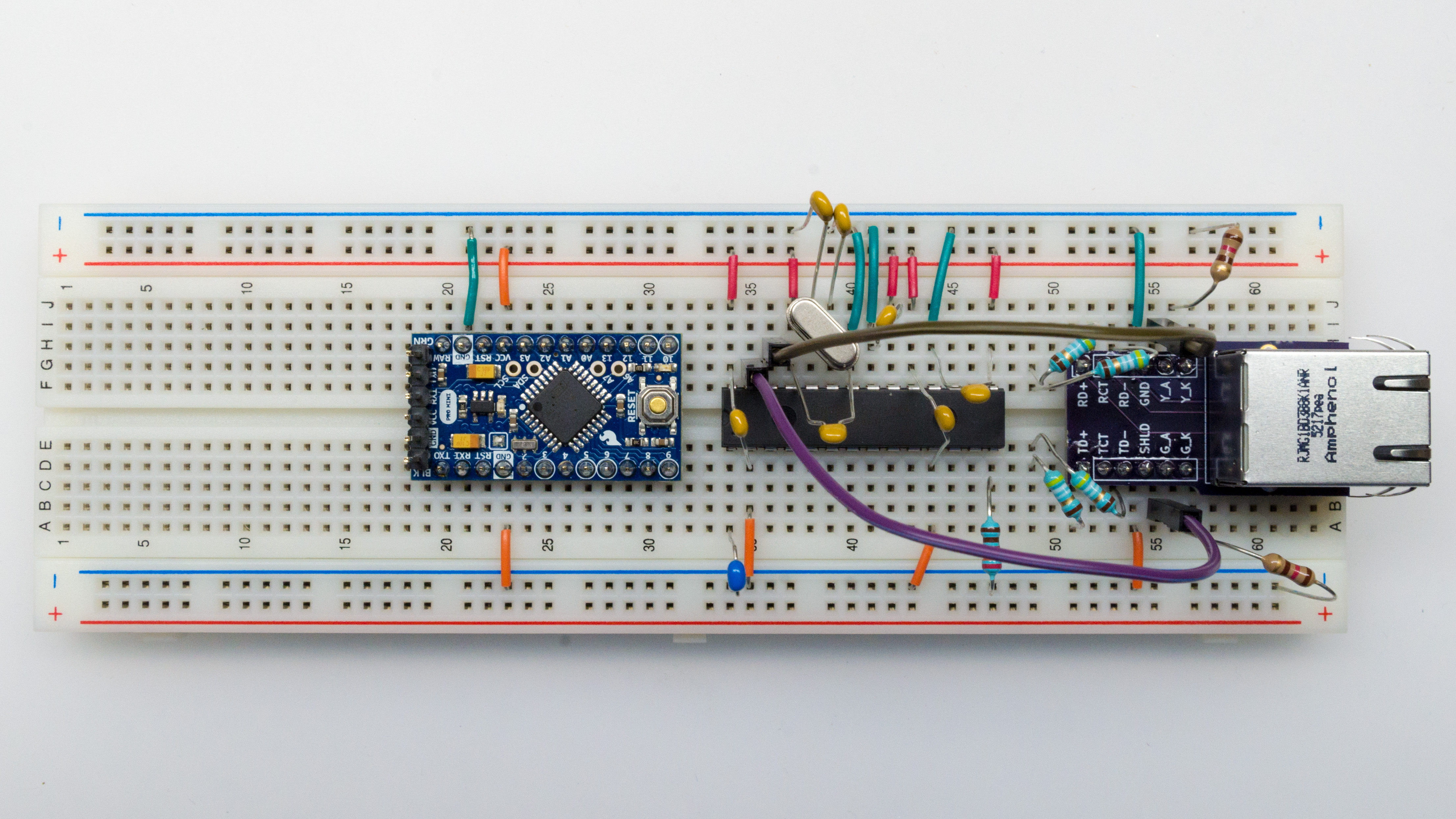
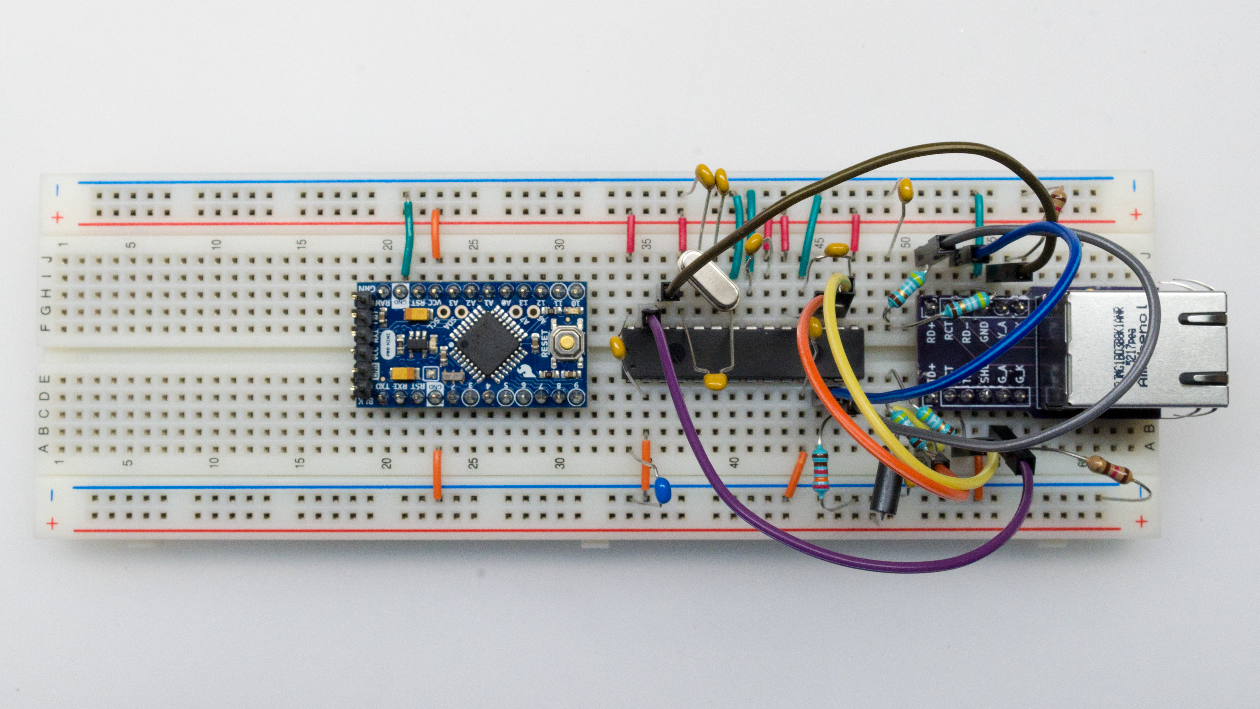
Add LED wires and LED resistors.
- G_A to pin 27 (LEDA).
- Y_A to pin 26 (LEDB).
- G_K and Y_K each through a 120 Ohm resistor to GND.
Add 2.32K resistor between RBIAS (pin 14) and GND.
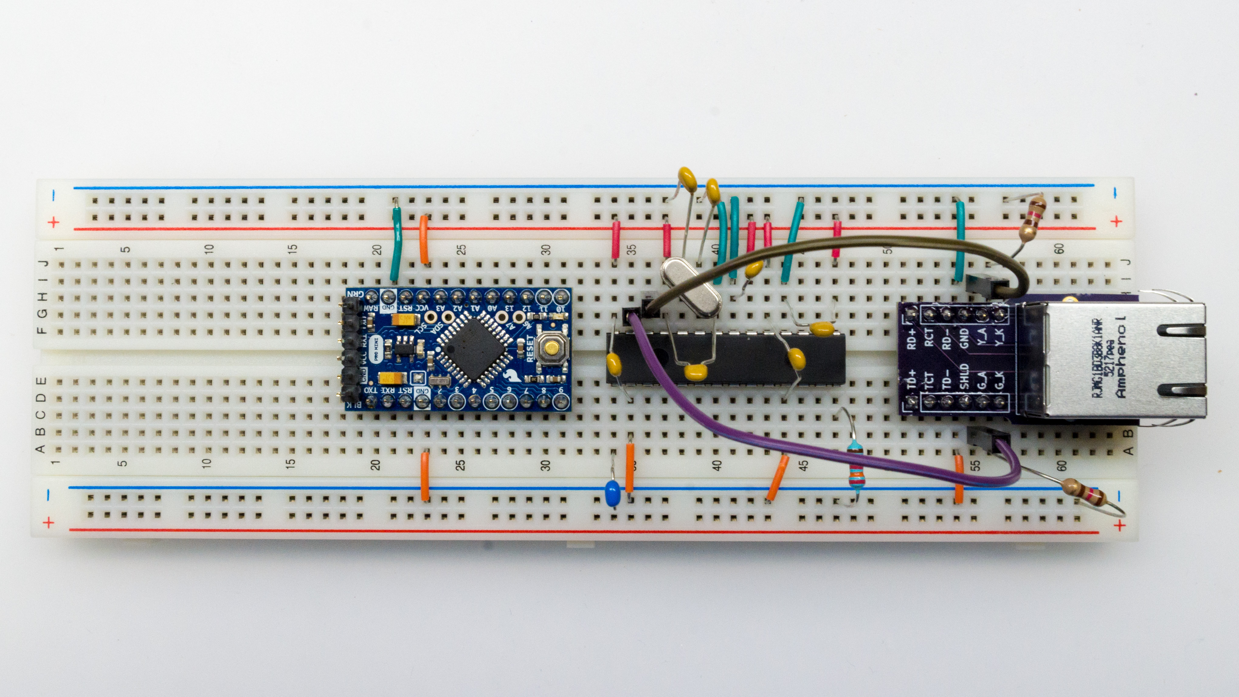
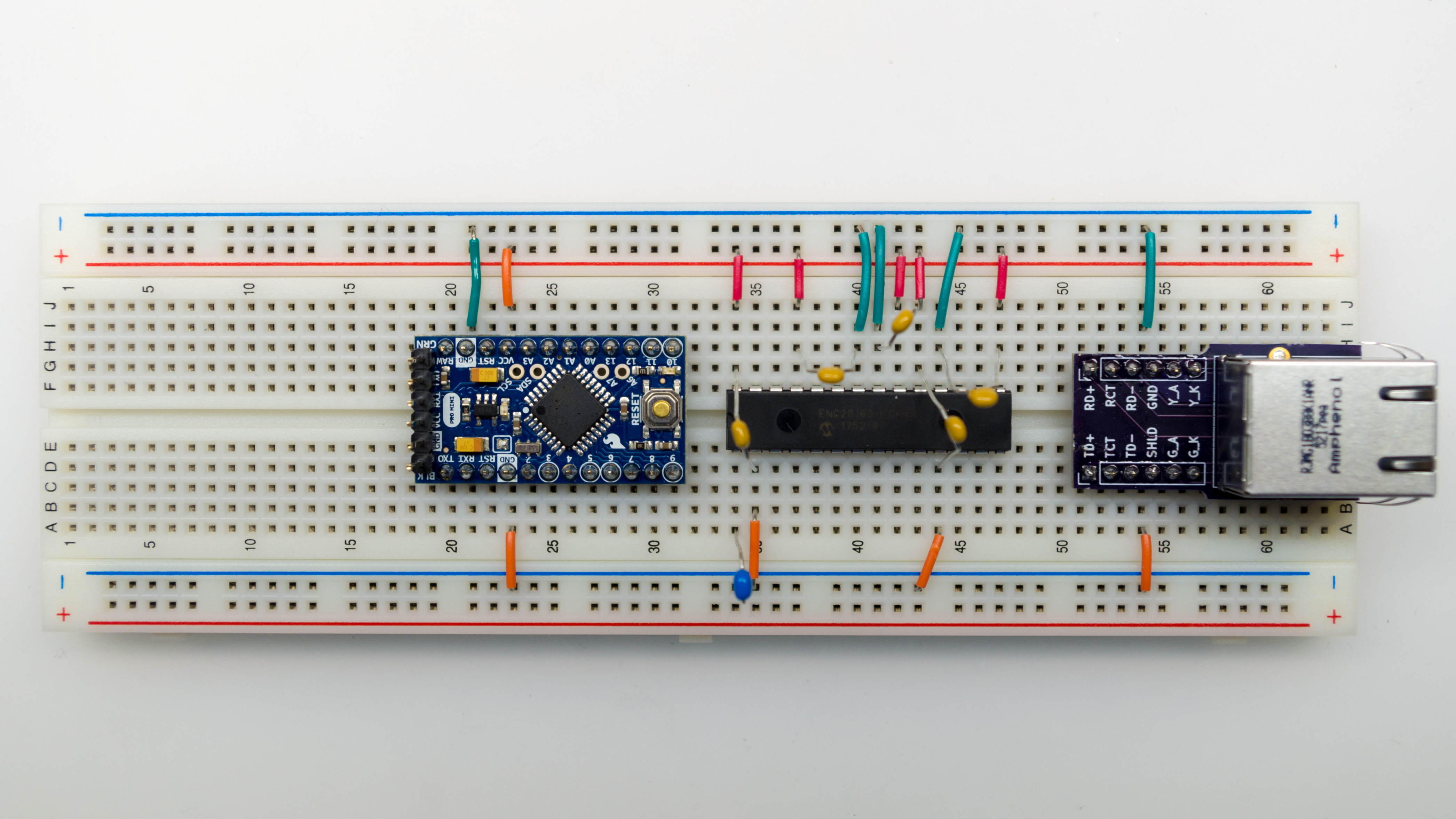
Add resistors and capacitors to MagJack.
- 49.9 Ohm resistors between TD+ and TCT, and between TCT and TD-.
- 0.1µF capacitor between TCT and GND. (*)
- 49.9 Ohm resistors between RD+ and an intermediate node, and between that intermediate node and RD-.
- 0.1µF capacitor between that intermediate node and GND. (*)
(*) Sorry, capacitors aren’t shown until photo for next step.
Add ferrite bead between TCT and 3.3V.
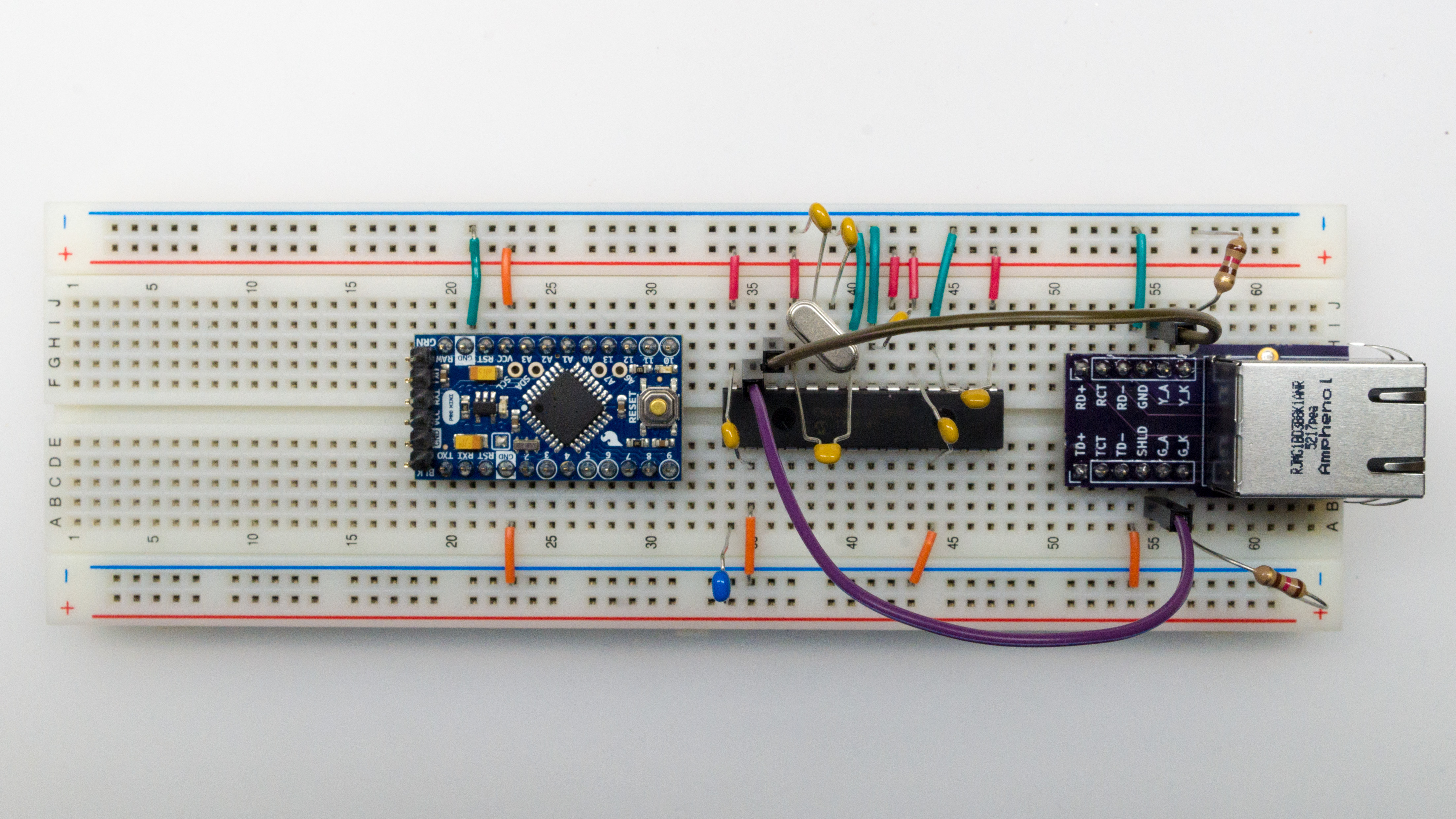
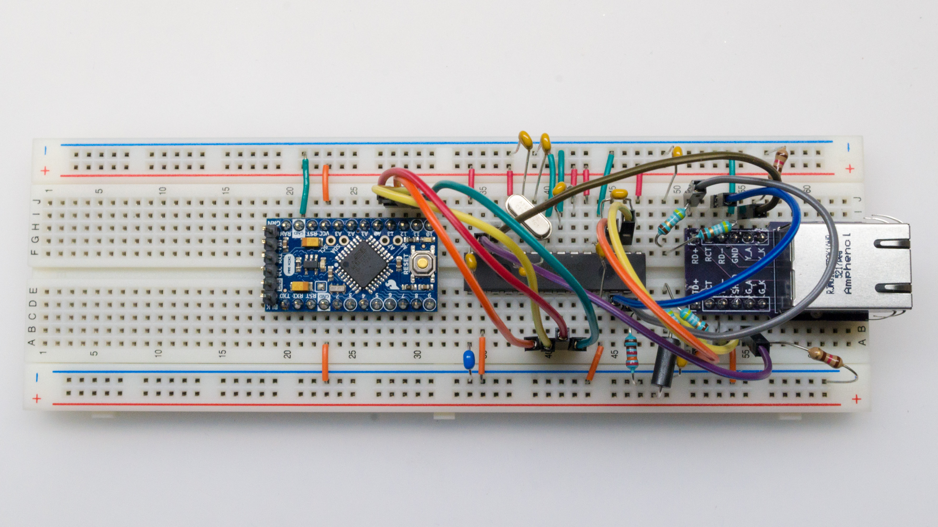
Add TX and RX wires.
- Between TD+ on Magjack, and TPOUT+ (pin 17) on ENC28J60.
- Between TD- on Magjack, and TPOUT- (pin 16) on ENC28J60.
- Between RD+ on Magjack, and TPIN+ (pin 13) on ENC28J60.
- Between RD- on Magjack, and TPIN- (pin 12) on ENC28J60.
Connect SPI pins to microcontroller.
- Between SI (pin 7) on ENC28J60 and pin 11 on Arduino Pro Mini.
- Between SO (pin 6) on ENC28J60 and pin 12 on Arduino Pro Mini.
- Between SCK (pin 8) on ENC28J60 and pin 13 on Arduino Pro Mini.
- Between CS (pin 9) on ENC28J60 and pin 10 on Arduino Pro Mini.
Connect power buses on the two sides of the breadboard together.
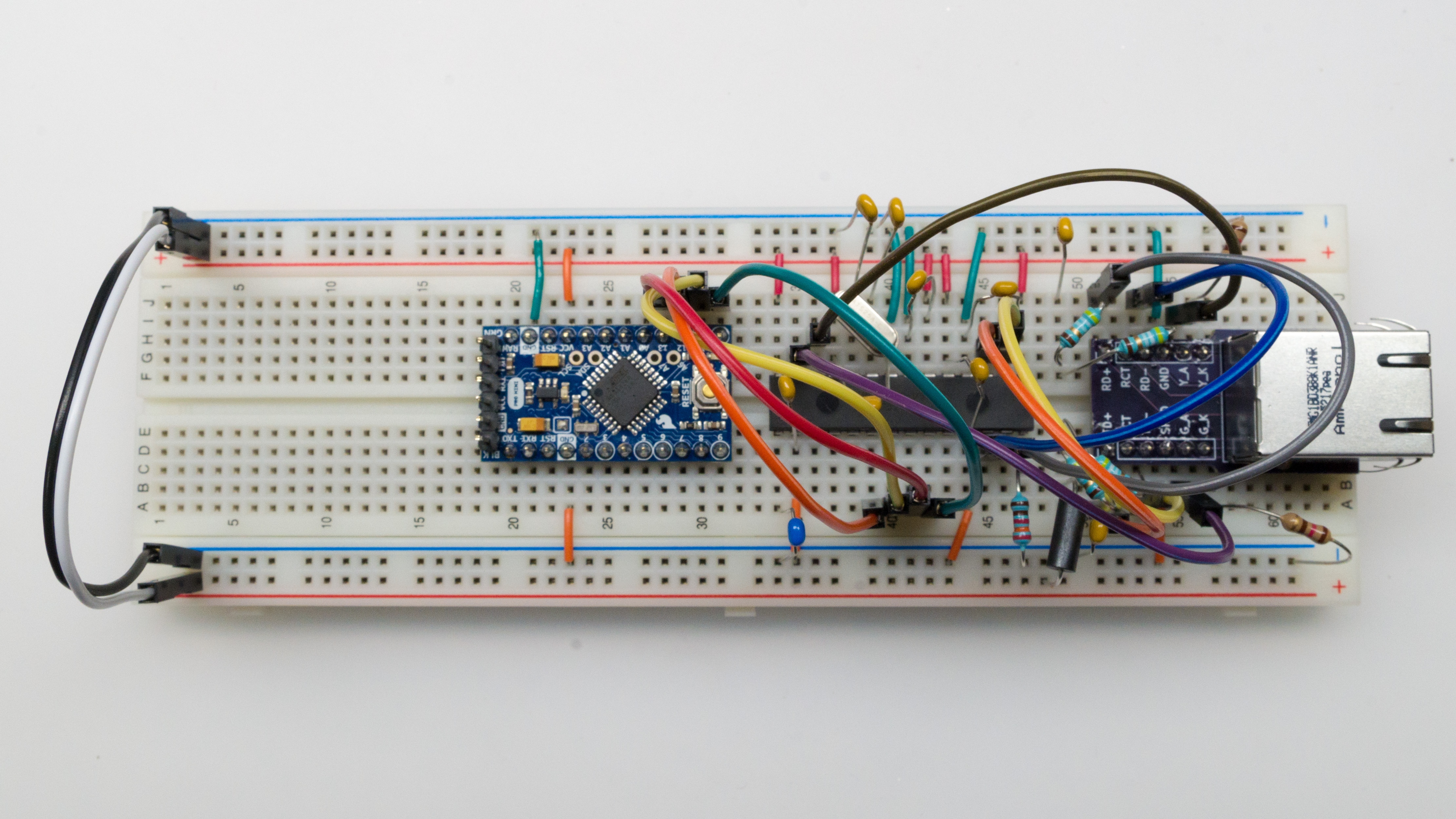
That’s it for the hardware. The second post will cover software and testing.