Rust on SAMD11
Previously, I’ve posted about how to run Arduino code on a SAMD11 on a breadboard, and about how to run Rust code on a Feather M4. This post just combines those two ideas, and shows how to run Rust code on a SAMD11 on a breadboard.
I’m going to be using the 14-pin ATSAMD11C14A, which is supported by the samd11_bare crate. (The 20-pin ATSAMD11D14AS I used before is not currently supported by Rust.)
Hardware setup
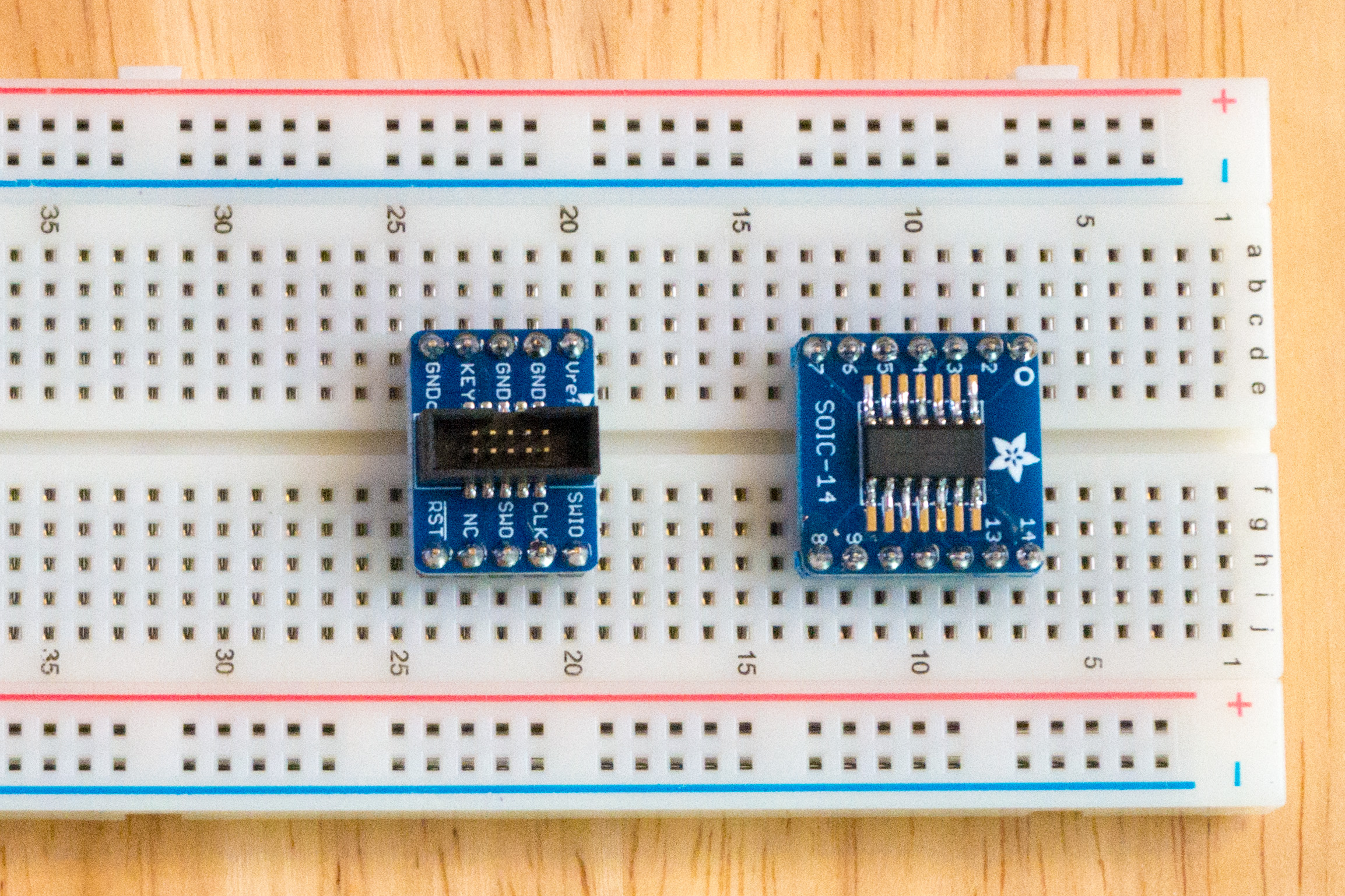
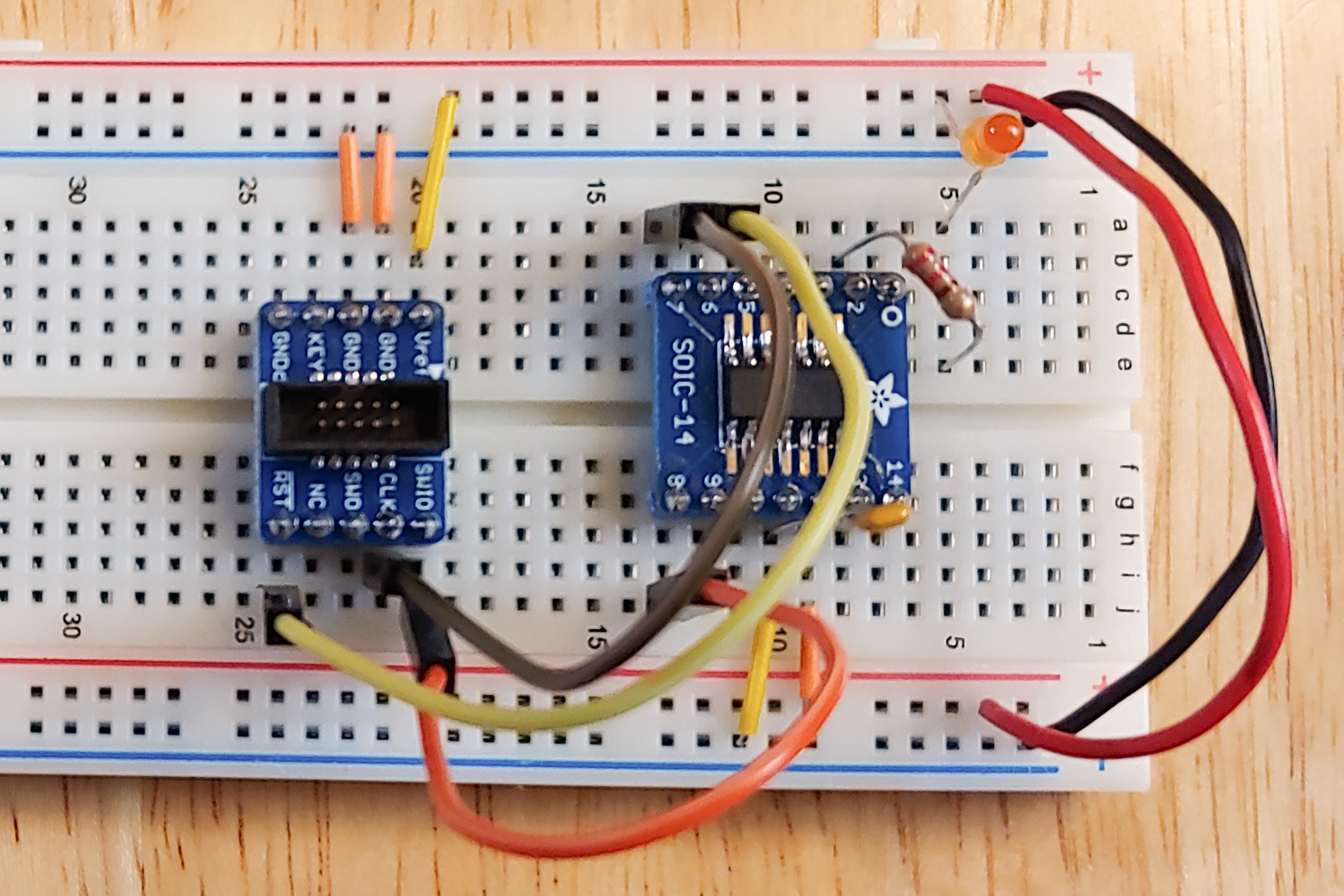
I started out by soldering the ATSAMD11C14A to a SOIC-14 breakout, and then putting that and a SWD connector breakout on a breadboard.
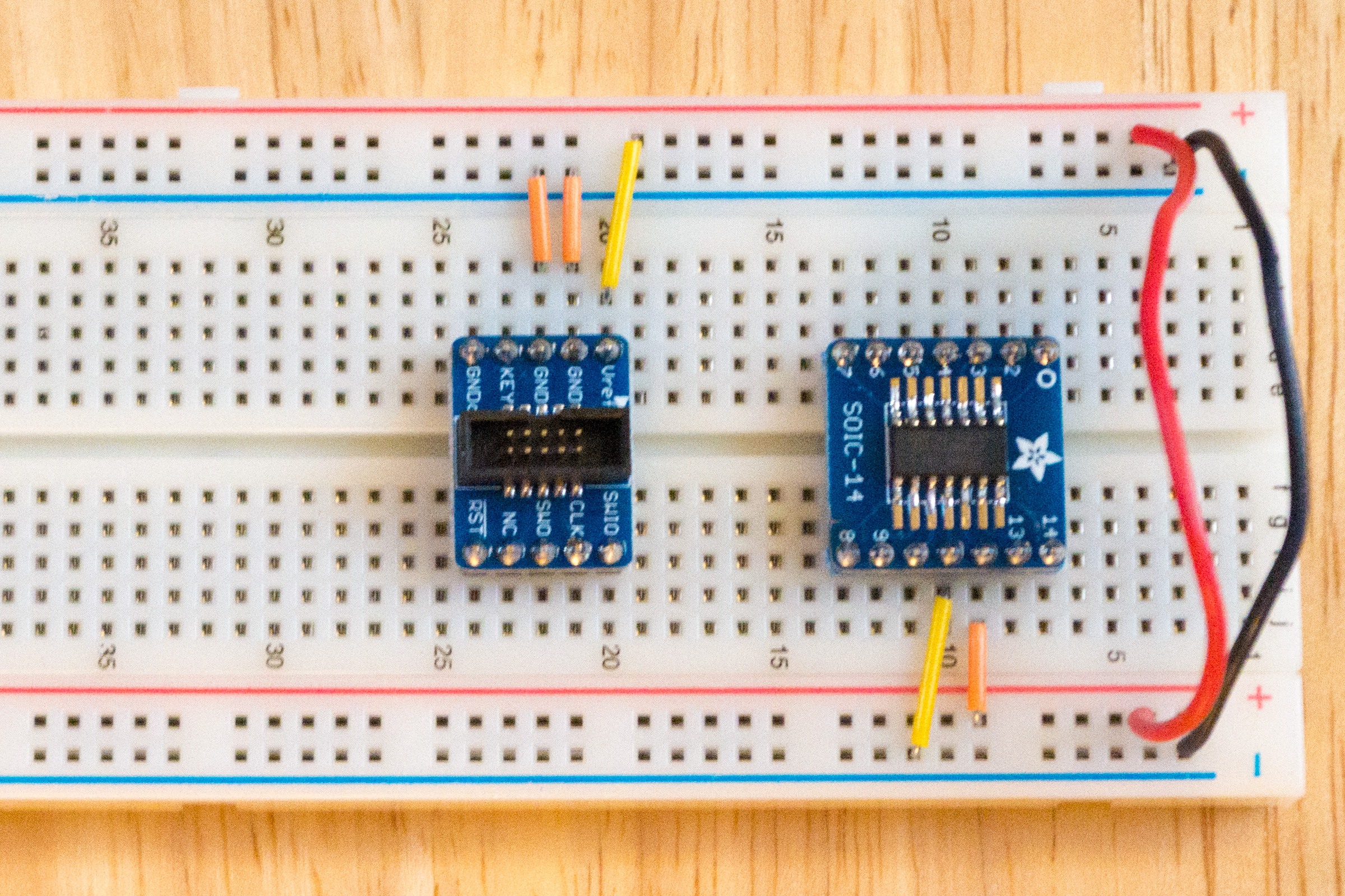
Next, I wired up power and ground. On the SWD breakout, the two “GND” pins go to ground, and the “Vref” pin goes to power. On the ATSAMD11C14A, pin 12 goes to power, and pin 11 goes to ground. I also added wires to connect the two power buses together and the two ground buses together.
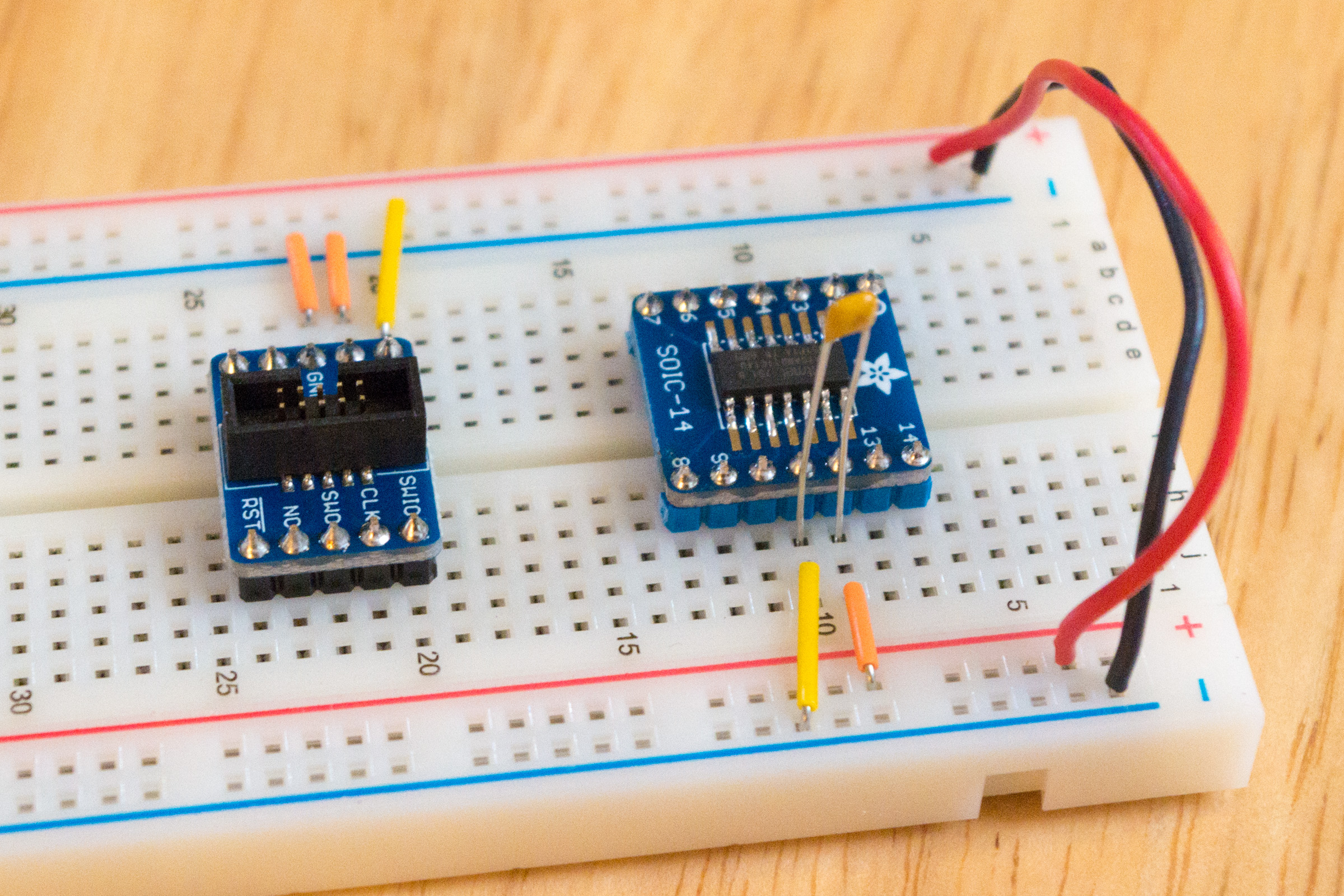
After that, I added a 0.1μF capacitor between pins 11 and 12 on the ATSAMD11C14A.
Next, I wired up the debug pins between the SWD breakout and the microcontroller. RST goes to pin 6, CLK goes to pin 7, and SWIO goes to pin 8.
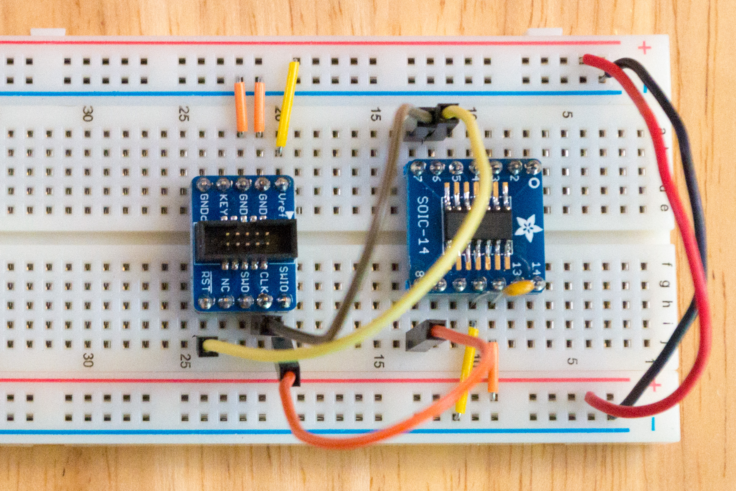
Finally, I added an LED to pin 2 of the microcontroller. I connected one end of a 220Ω resistor to pin 2, and I connected the other end to a spare row on the breadboard. Then I connected the LED’s cathode (short pin, flat side) to the row the resistor is connected to, and I connected the LED’s anode (long pin, round side) to the positive power rail.
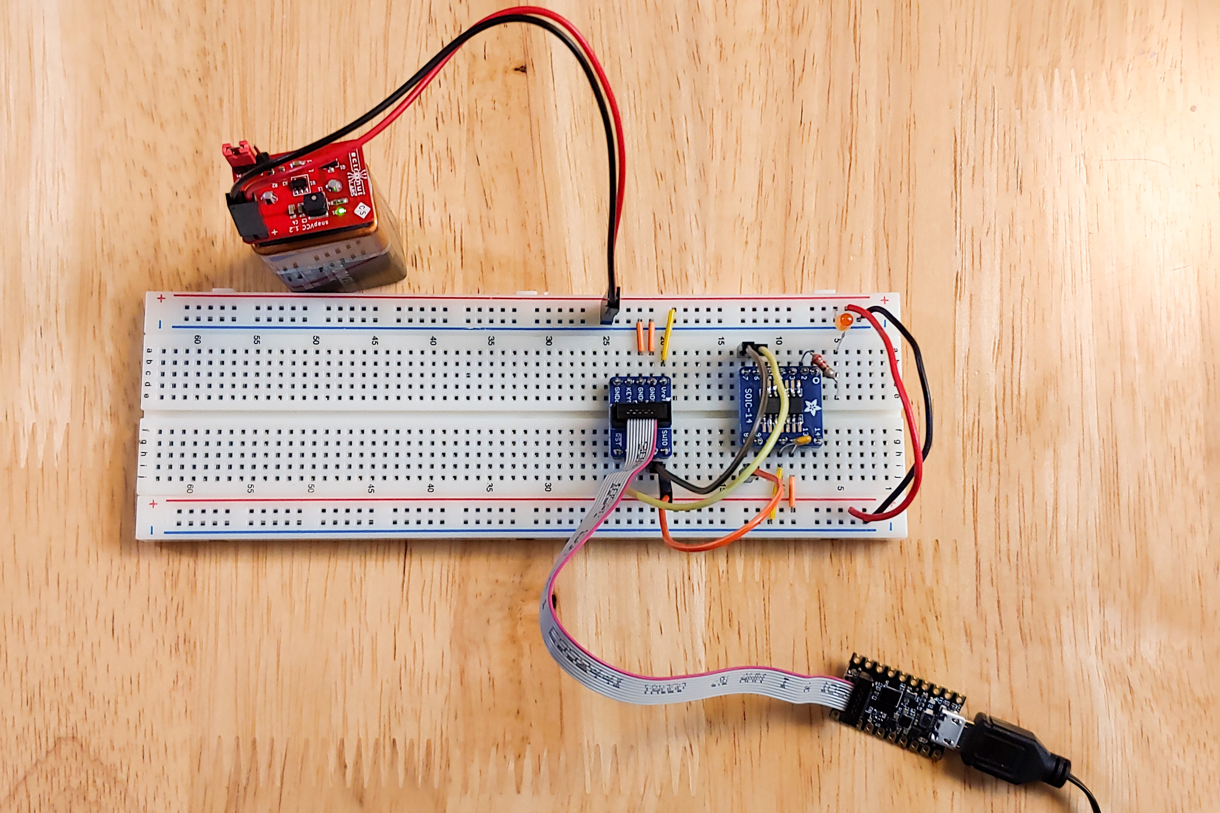
Now, to get ready to program the ATSAMD11C14A, I hooked up my trusty SnapVCC (set on 3.3V) to the power and ground rails of the breadboard. And I got out my MAX32625PICO and connected it to the debug header.
Software setup
Make sure you have Rust installed, and then install thumb6 support:
$ rustup target add thumbv6m-none-eabiNext, you’ll need an ARM toolchain. Download the ARM gcc toolchain from ARM’s website, and then install it something like this:
$ cd /opt
$ tar -xf ~/Desktop/gcc-arm-none-eabi-9-2020-q2-update-x86_64-linux.tar.bz2
$ export PATH="/opt/gcc-arm-none-eabi-9-2020-q2-update/bin:$PATH"
See this bug for more information.
Clone the Rust atsamd repository:
$ git clone https://github.com/atsamd-rs/atsamd.git
$ cd atsamd/boards/samd11_bare
In the boards/samd11_bare directory, create a file named openocd.cfg with the following contents:
source [find interface/cmsis-dap.cfg]
transport select swd

set CHIPNAME at91samd11c14a
source [find target/at91samdXX.cfg]

reset_config  srst_nogate

adapter_nsrst_delay 100
adapter_nsrst_assert_width 100

init
targets
reset halt

at91samd bootloader 0
program blinky_basic.bin verify
reset
shutdown
Then, in that directory, do:
$ cargo build --release --example blinky_basic
$ arm-none-eabi-objcopy -O binary target/thumbv6m-none-eabi/release/examples/blinky_basic blinky_basic.bin
Make sure the MAX32625PICO (our debug probe) is connected to the computer’s USB port, and the breadboard is getting 3.3V power (from the SnapVCC, or other 3.3V power source). Then, upload the program with:
$ openocdThis should start blinking the LED on the breadboard.