Breadboard SAMD11, part 1
This is part 1 of 2.
I’ve been using AVR chips on my own boards with the Arduino toolchain for nearly a couple of years now. However, I’m interested in using ARM chips on my own boards, as well. And although there are a number of things about Arduino that I don’t like, I haven’t found anything that beats it for portability. So I want to use Arduino with ARM chips on my own boards.
Luckily, there’s an Arduino core available for SAM chips (Atmel/Microchip’s line of ARM Cortex-M microcontrollers). In particular, the ATSAMD11D14AS seems like a good place to start, since it is available in a SOIC-20 package, which should be relatively easy to solder, as surface-mount goes. (As far as I can tell, there are no ARM microcontrollers available in DIP packages.)
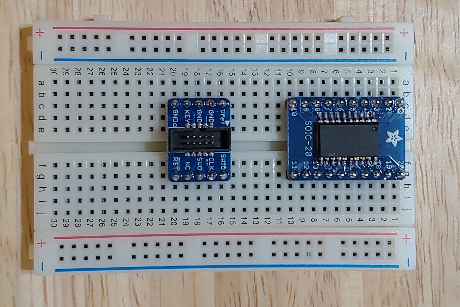
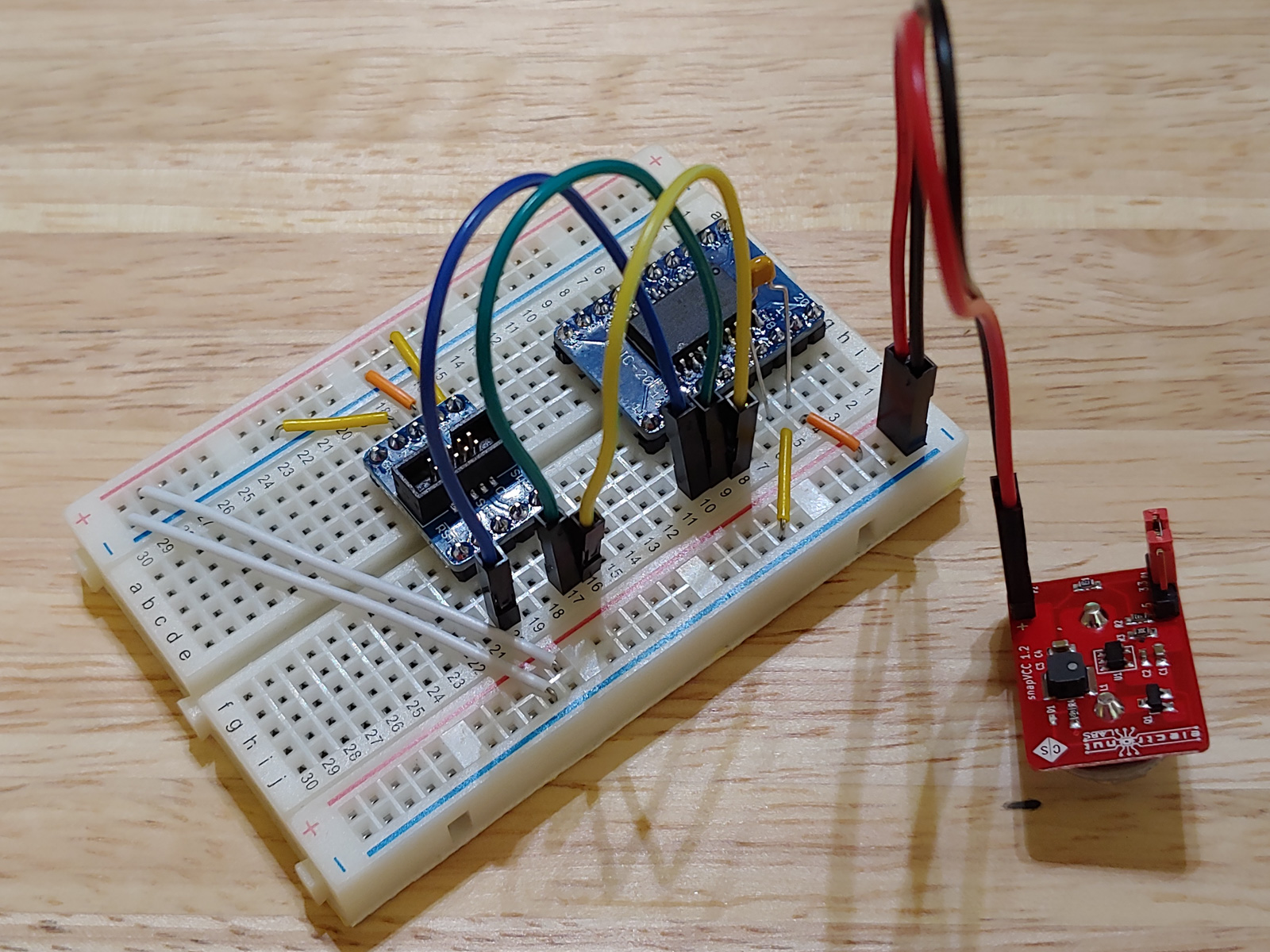
So, I got an ATSAMD11D14AS and a SOIC-20 breakout board, and soldered the former onto the latter. I also got a SWD connector breakout board, and set them up on my breadboard.
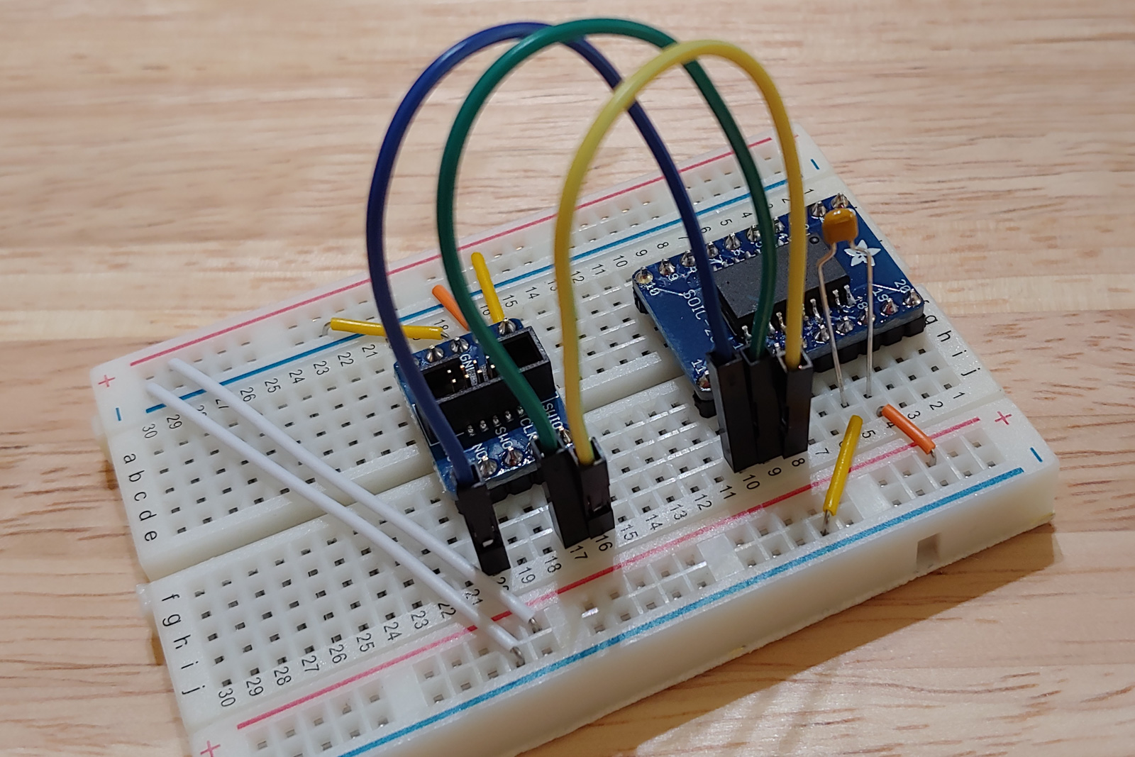
Next, I added wires for VDD and GND. VDD connects to pin 17 of the SAMD11 and to the Vref pin of the SWD breakout. GND connects to pin 16 of the SAMD11 and to both of the pins labeled GND on the SWD breakout.
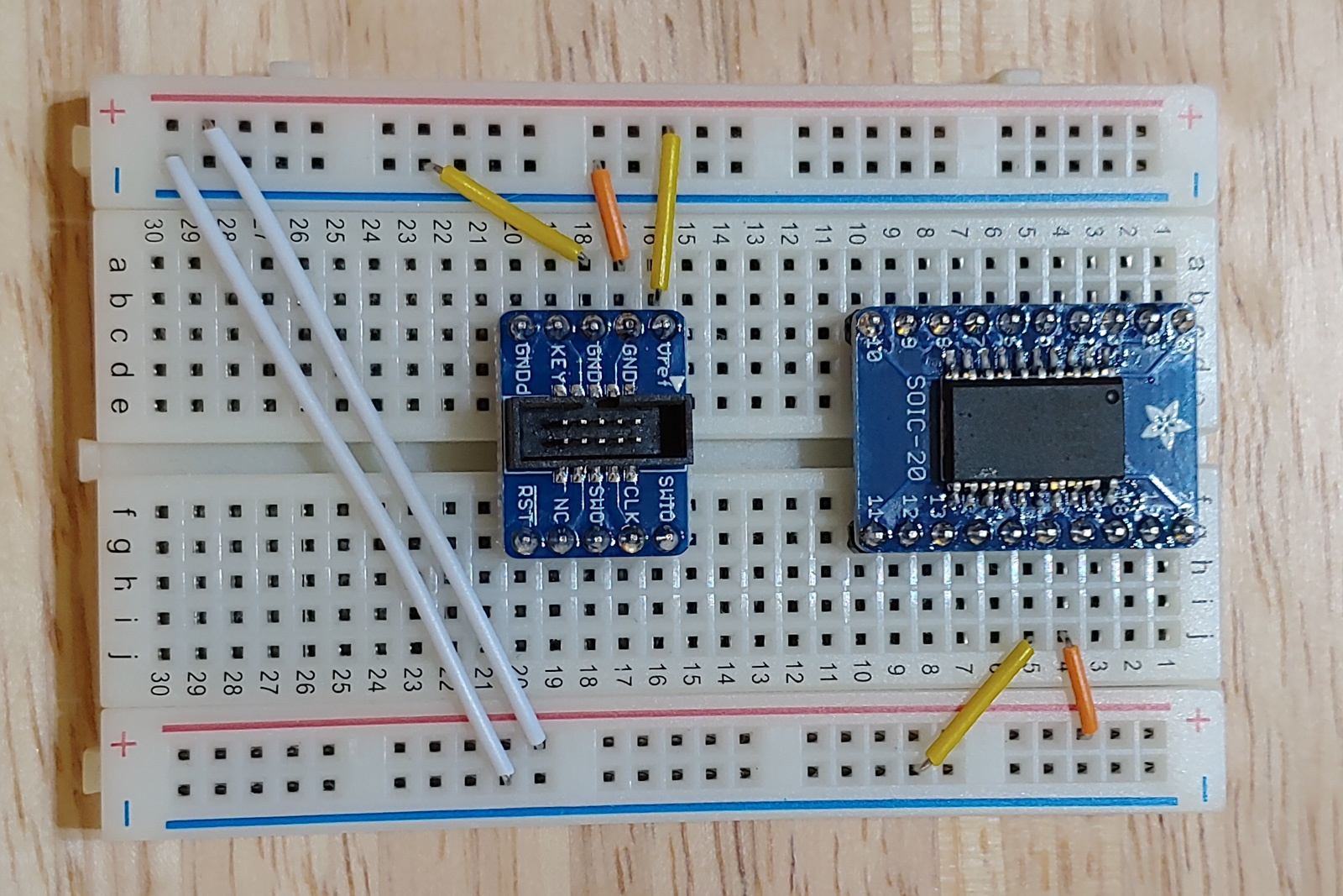
I also added a 0.1μF decoupling capacitor across pins 16 and 17 of the SAMD11.
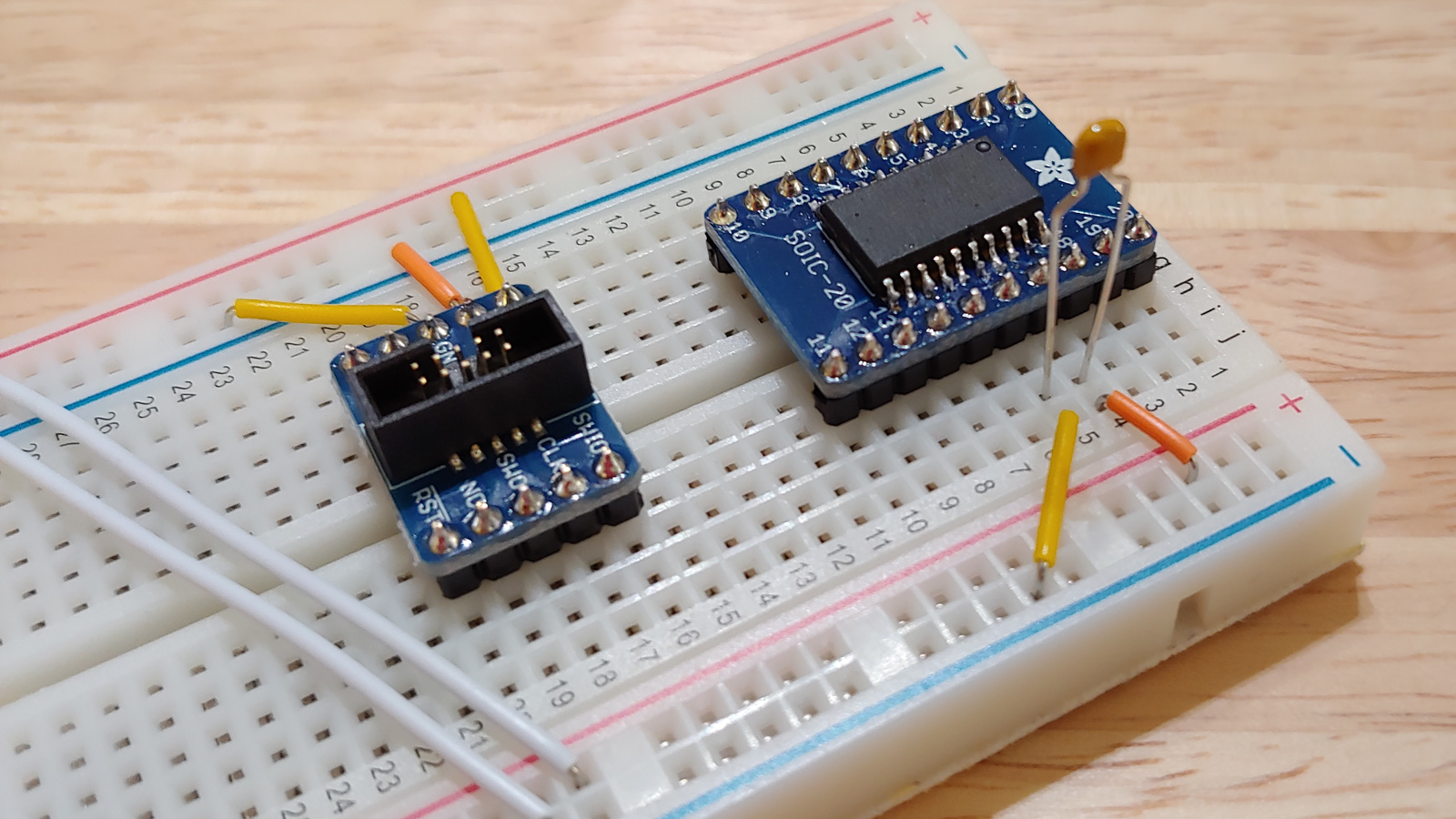
Next, I connected RST to pin 11, CLK to pin 12, and SWIO to pin 13.
To power the SAMD11, I used a SnapVCC set for 3.3V.
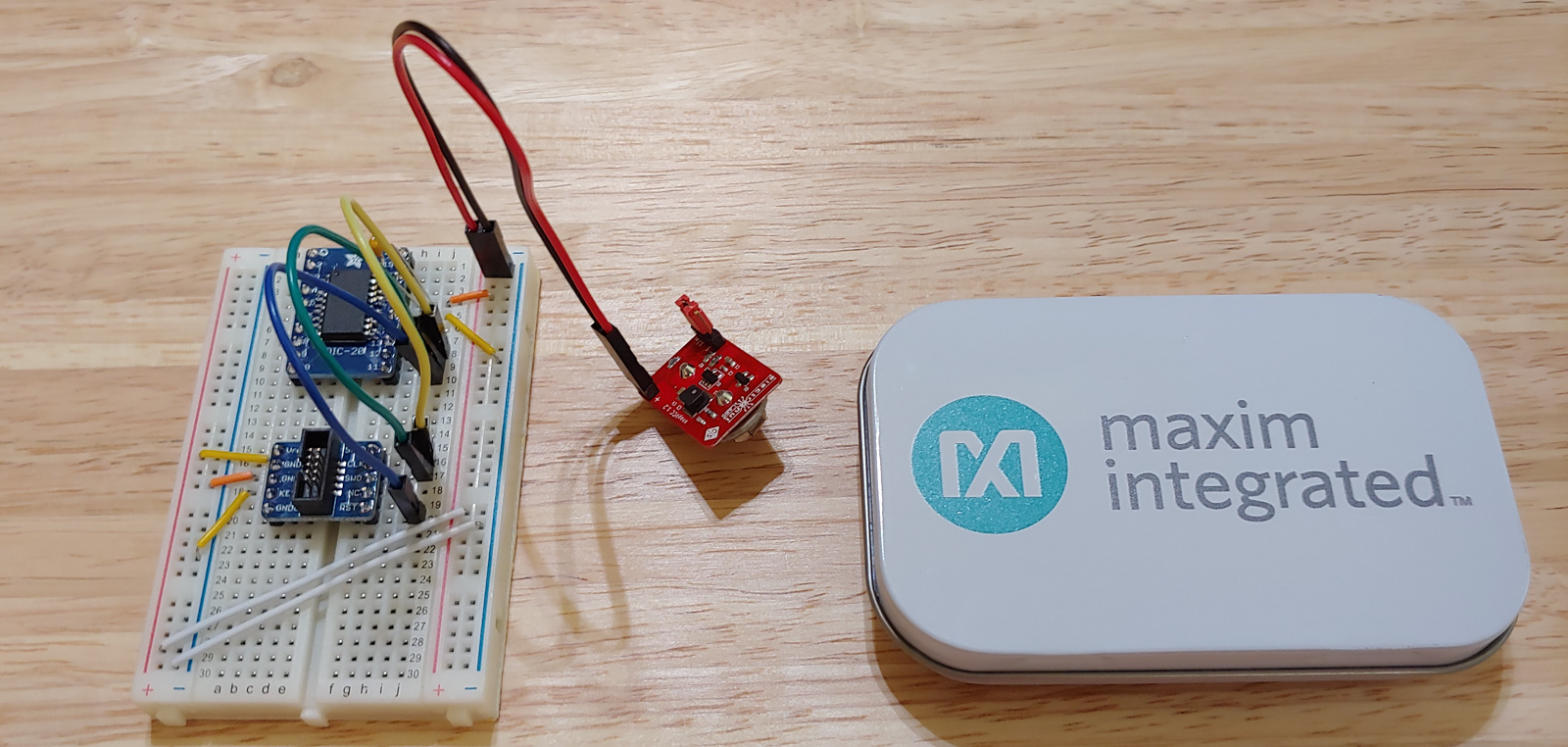
To program the bootloader into the SAMD11, you need a debug probe of some sort to connect the SWD connector to a computer. There are debug probes out there which are crazy expensive, or which are only licensed for non-commercial use. But there’s no need for any of that silliness. There’s a perfectly good debug probe for $11.70, the MAX32625PICO. It’s super-tiny and comes in a cute little tin. The MAX32625PICO is actually a full-blown development board that you can run your own code on, but the default firmware it comes flashed with makes it behave like a CMSIS-DAP probe, which is exactly what we want.
(It’s also possible to use a Raspberry Pi instead of a debug probe. I haven’t tried this, but Adafruit has an article about it.)
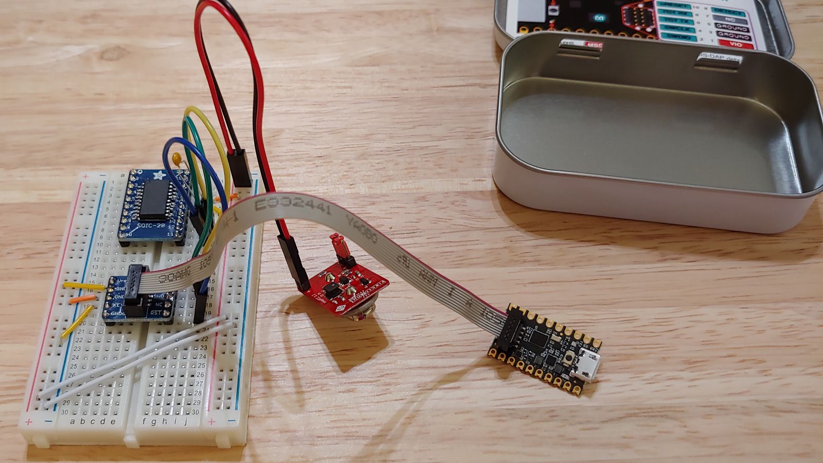
I connected the MAX32625PICO to the SWD breakout board with the supplied ribbon cable.
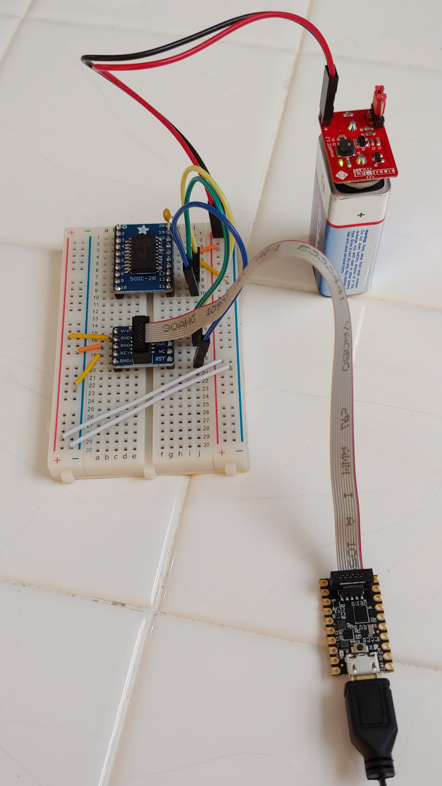
Finally, I plugged the MAX32625PICO into my MacBook Pro, and I attached a 9V battery to the SnapVCC.
The software that I used to talk to the debug probe is OpenOCD. I installed OpenOCD on my Mac with brew install openocd. That got me the latest relased version of OpenOCD, version 0.10.0. That version worked fine for me.
Then I created a new directory containing two files: the bootloader for the SAMD11, and a file openocd.cfg with the following contents:
source [find interface/cmsis-dap.cfg]
transport select swd

set CHIPNAME at91samd11d14ass
source [find target/at91samdXX.cfg]

reset_config  srst_nogate

adapter_nsrst_delay 100
adapter_nsrst_assert_width 100

init
targets
reset halt

at91samd bootloader 0
program sam_ba_Generic_D11D14AS_SAMD11D14AS.bin verify
at91samd bootloader 4096
reset
shutdown
This config file is based on the one in Adafruit’s tutorial. I’ve just changed it to use CMSIS-DAP for the interface, and SAMD11 for the chip.
Then I typed sudo openocd in that directory, and it successfully programmed the bootloader into the SAMD11:
Open On-Chip Debugger 0.10.0
Licensed under GNU GPL v2
For bug reports, read
	http://openocd.org/doc/doxygen/bugs.html
none separate
adapter speed: 400 kHz
cortex_m reset_config sysresetreq
none separate
adapter_nsrst_delay: 100
adapter_nsrst_assert_width: 100
Info : CMSIS-DAP: SWD  Supported
Info : CMSIS-DAP: Interface Initialised (SWD)
Info : CMSIS-DAP: FW Version = 1.0
Info : SWCLK/TCK = 0 SWDIO/TMS = 1 TDI = 0 TDO = 0 nTRST = 0 nRESET = 0
Info : CMSIS-DAP: Interface ready
Info : clock speed 400 kHz
Info : SWD DPIDR 0x0bc11477
Info : at91samd11d14ass.cpu: hardware has 4 breakpoints, 2 watchpoints
    TargetName         Type       Endian TapName            State
--  ------------------ ---------- ------ ------------------ ------------
 0* at91samd11d14ass.cpu cortex_m   little at91samd11d14ass.cpu halted
target halted due to debug-request, current mode: Thread
xPSR: 0x51000000 pc: 0xfffffffe msp: 0xfffffffc
target halted due to debug-request, current mode: Thread
xPSR: 0x51000000 pc: 0xfffffffe msp: 0xfffffffc
** Programming Started **
auto erase enabled
Info : SAMD MCU: SAMD11D14ASU (16KB Flash, 4KB RAM)
wrote 4096 bytes from file sam_ba_Generic_D11D14AS_SAMD11D14AS.bin in 1.000038s (4.000 KiB/s)
** Programming Finished **
** Verify Started **
verified 3904 bytes in 0.432693s (8.811 KiB/s)
** Verified OK **
shutdown command invoked
The next step will be to add a USB port to our breadboard, so we can upload a sketch onto the SAMD11 from the Arduino IDE. I’ll cover that in the next part.