Breadboard SAMD11, part 2
This is part 2 of 2.
In part 1, I showed how to burn a bootloader onto an ATSAMD11D14AS microcontroller, using OpenOCD and an inexpensive CMSIS-DAP probe.
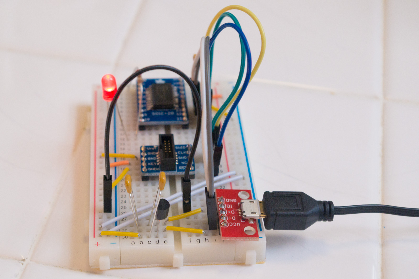
In this part, I will add a USB port and an LED to my breadboard, and upload an Arduino sketch to the ATSAMD11D14AS over USB.
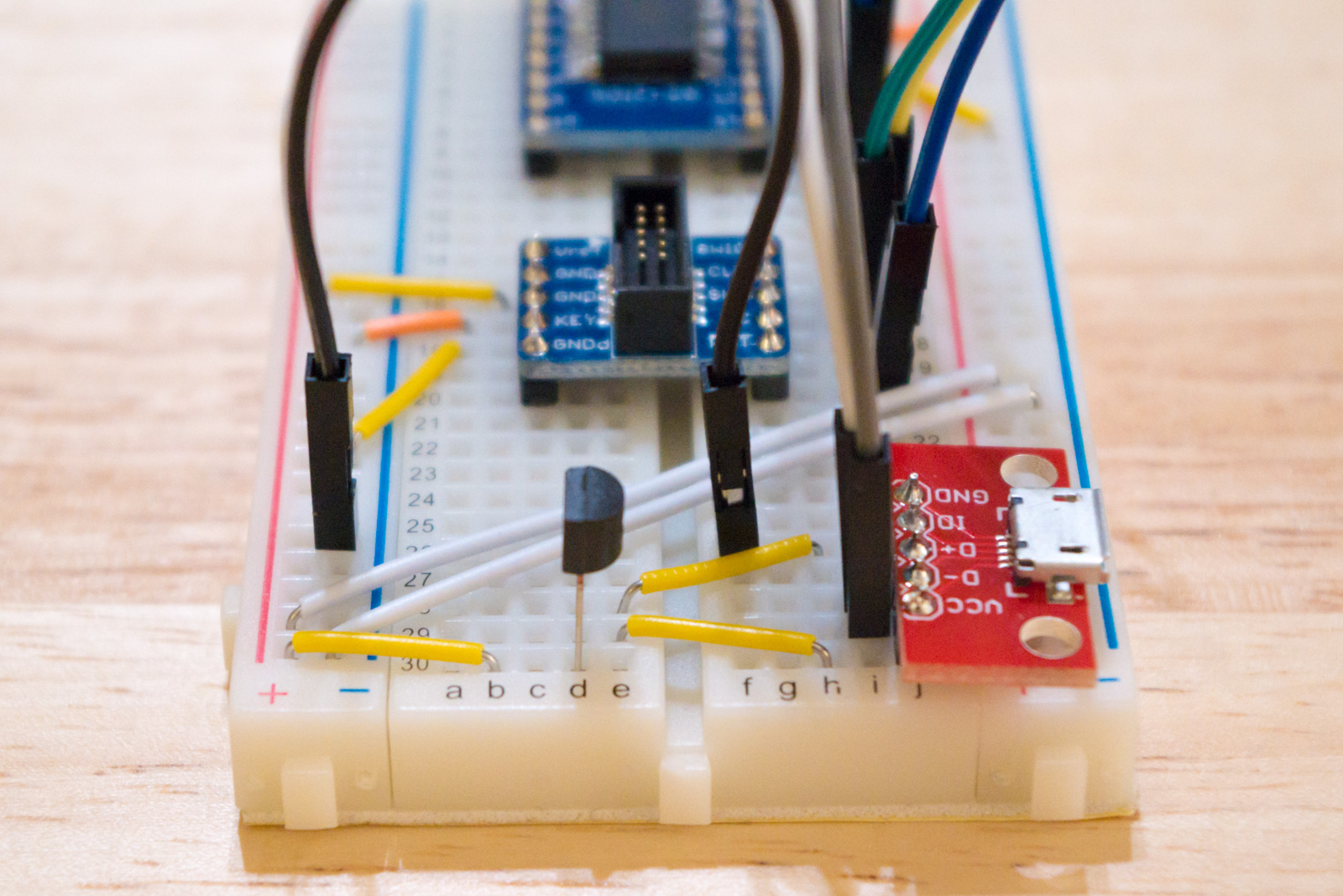
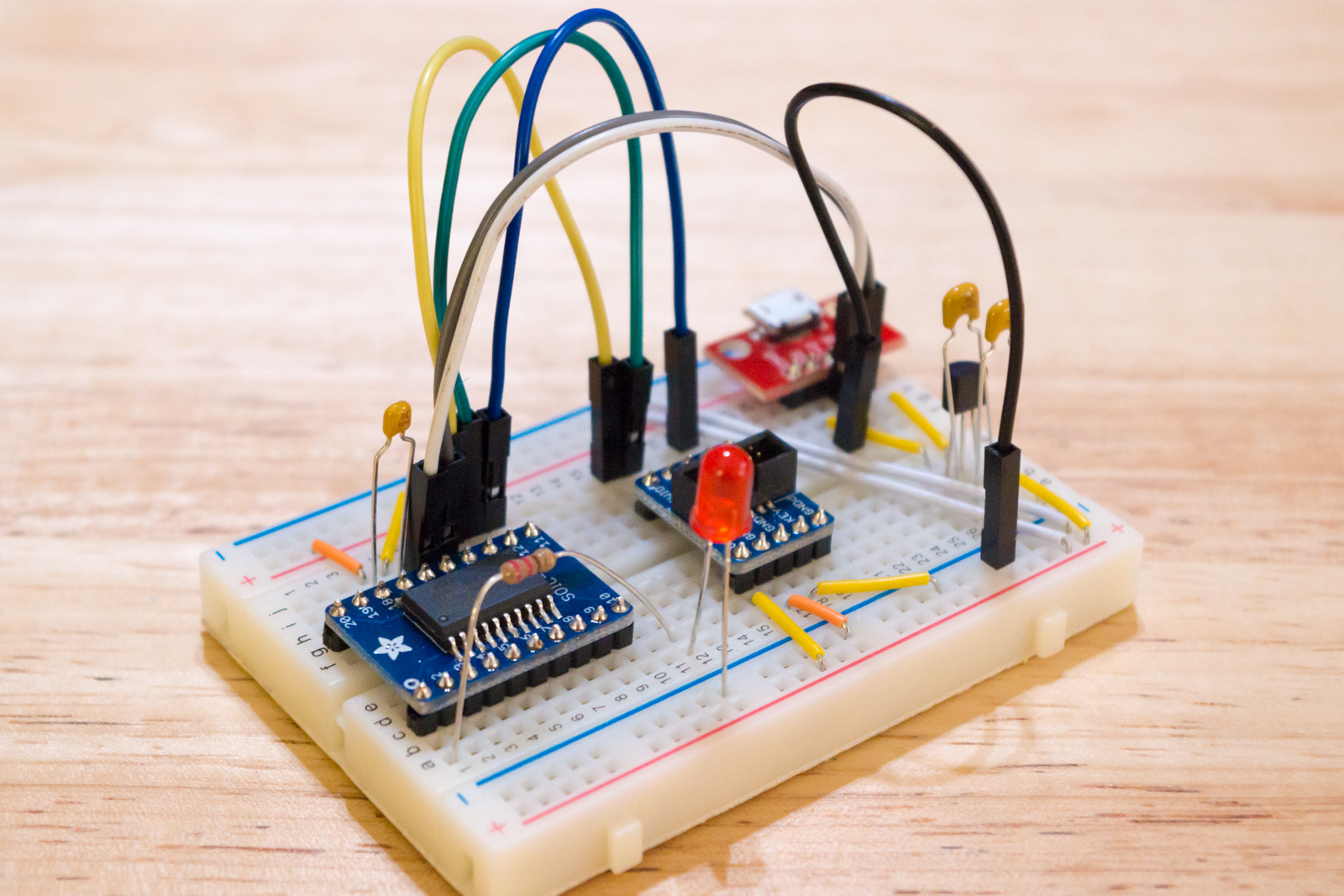
First, I added a SparkFun microB USB Breakout to my breadboard.
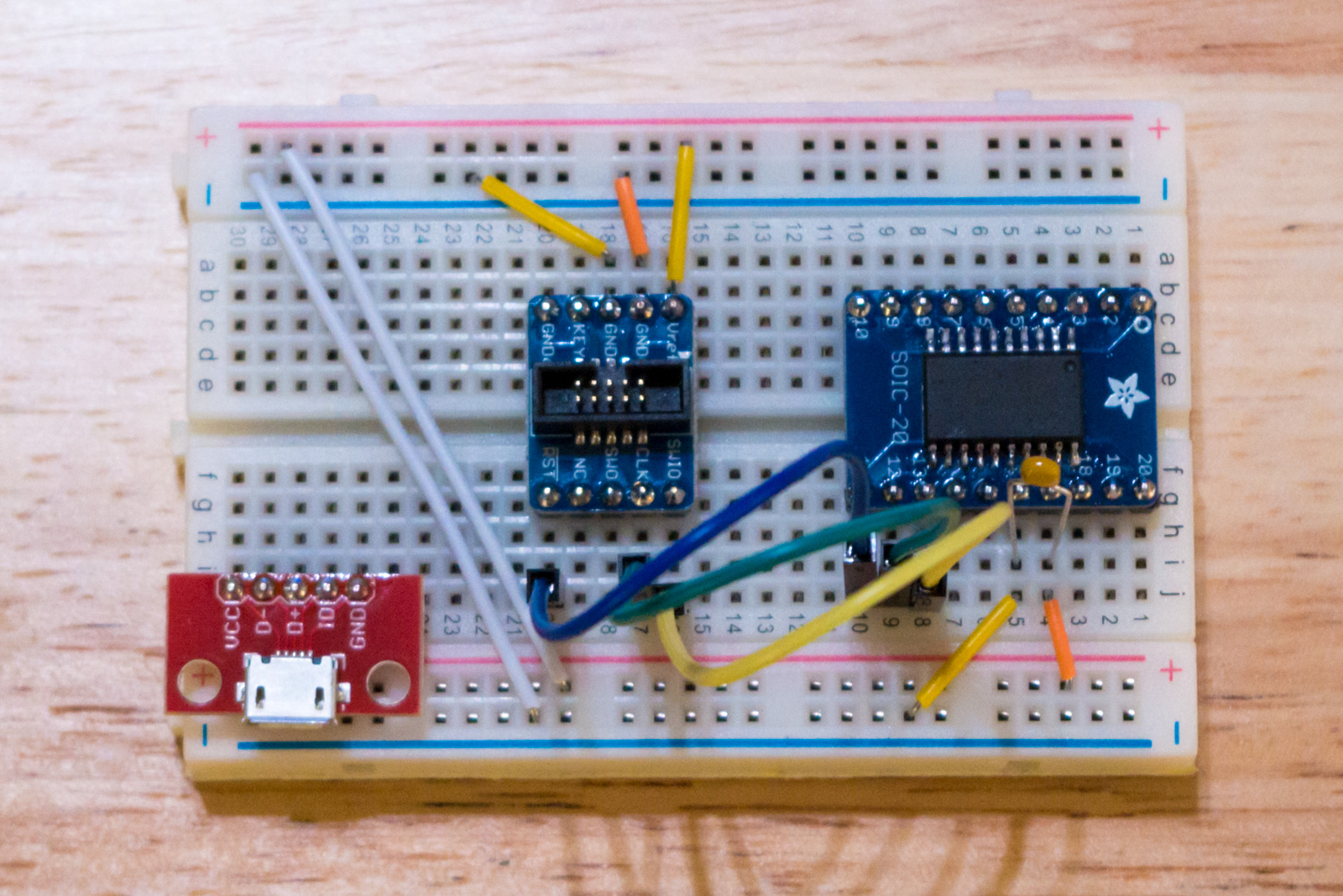
I connected pin 14 of the SAMD11 to D- of the USB breakout, and pin 15 of the SAMD11 to D+ of the USB breakout.
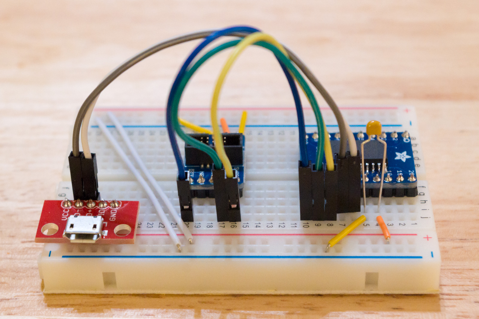
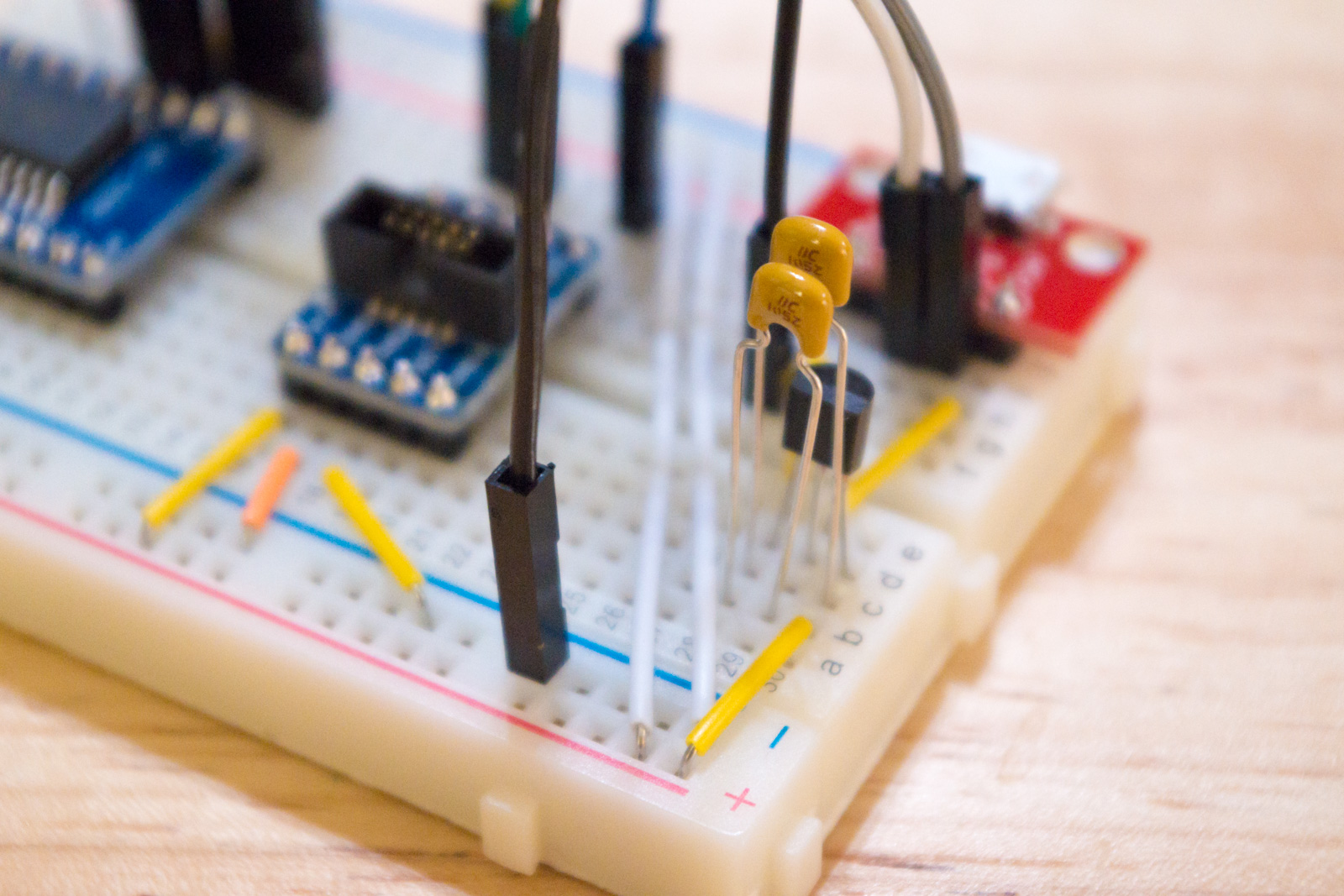
Next, I added a 3.3V, 250mA voltage regulator. Pin 1 of the voltage regulator connects to both the GND pin of the USB breakout, and the “-” rail of the breadboard. Pin 2 of the voltage regulator connects to the VCC pin of the USB breakout. Pin 3 of the voltage regulator connects to the “+” rail of the breadboard.
Then I put a 1μF ceramic capacitor between pin 1 and pin 2 of the regulator, and another one between pin 1 and pin 3. (These are suggested by the regulator’s datasheet.)
Finally, I connected a red LED to pin 1 of the SAMD11 (which is Arduino digital pin 5) via a 220Ω resistor.
Next, on my Mac, I needed to install the Mattairtech SAMD Arduino core. This is basically a matter of adding https://www.mattairtech.com/software/arduino/package_MattairTech_index.json to the Boards Manager URLs in the Arduino IDE, and then using the Boards Manager to install “MattairTech SAM D|L|C Core for Arduino.”
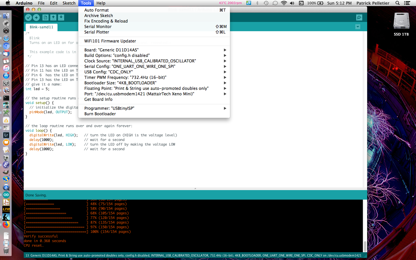
After that, I plugged the breadboard into the USB port on my computer, and selected the correct serial port (which shows up as MattairTech Xeno Mini) in the Tools menu.
I opened the standard Arduino Blink sketch, and changed the pin number for the LED from 13 to 5.
/*
  Blink
  Turns on an LED on for one second, then off for one second, repeatedly.

  This example code is in the public domain.
 */

// Pin 13 has an LED connected on most Arduino boards.
// Pin 11 has the LED on Teensy 2.0
// Pin 6  has the LED on Teensy++ 2.0
// Pin 13 has the LED on Teensy 3.0
// give it a name:
int led = 5;

// the setup routine runs once when you press reset:
void setup() {
  // initialize the digital pin as an output.
  pinMode(led, OUTPUT);
}

// the loop routine runs over and over again forever:
void loop() {
  digitalWrite(led, HIGH);   // turn the LED on (HIGH is the voltage level)
  delay(1000);               // wait for a second
  digitalWrite(led, LOW);    // turn the LED off by making the voltage LOW
  delay(1000);               // wait for a second
}
I made sure the board selected in the Tools menu was “Generic D11D14AS,” and that the other settings in the Tools menu looked okay. Then I just hit the upload button, and it uploaded the sketch.
And the LED blinks!